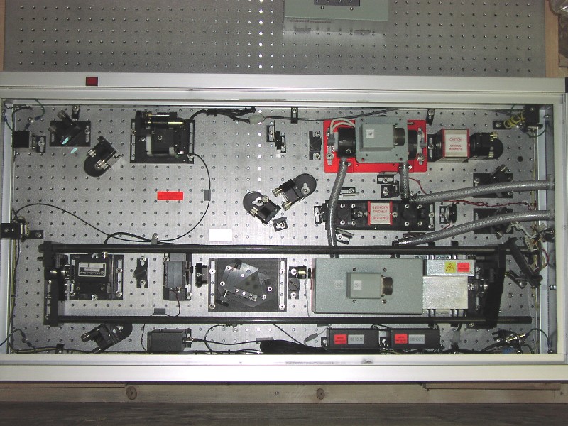
APOLLO Laser Plan View
This view shows the layout of all the laser optical components. Along the bottom is the laser cavity, defined by the long black carbon rods. The laser rod and flashlamps are contained within the large gray box near the right end of the cavity. To the right of this is the shielded Marx bank and Pockels cell responsible for dumping the cavity. To the left of the laser rod is the large delay prism for cavity-length adjustment, the saturable absorber for truncating the pulse, and the acousto-optic modulator that creates the pulse train. Along the very bottom wall is the photodiode used to detect build-up of optical energy, plus some power supplies (below the flashlamp housing). At upper right is the amplifier. In this case, the gray box cover has been removed to reveal the black cylindrical flashlamp/rod housing. At upper left is the gimballed crystal that produces second-harmonic light at 532 nm, followed by output optics.